The masonry wall panel element allows you to easily model, analyze and design masonry walls for in plane
Note:
Setting a maximum Bending Check (Axial & Bending) or a maximum Shear Check controls the rebar which the program chooses for the wall design. A value of 1.0 denotes that the program may choose a rebar layout that is at 100% of capacity.
Note:
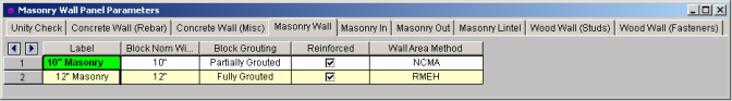
This is the nominal thickness of masonry walls. The program will subtract 3/8" from this value to get the actual thickness. This value is used, along with the value of grout / bar spacing, to determine the effective thickness of the wall. The effective thickness is based on table B3 of the Reinforced Masonry Engineering Handbook, by Amrhein, Copyright 1998.
This option defines how the wall is grouted. If "Partially Grouted" is chosen, then the spacing of grout will be based on the maximum bar spacing defined on the Masonry Out tab.
This defines whether the wall is reinforced or not.
This option defines where the wall area is taken from. The NCMA option pulls the "An" value from the NCMA TEK 141B document. The RMEH option pulls the "Equivalent Solid Thickness" value from Table B-3a and B-3b from the Reinforced Masonry Engineering Handbook, James Amrhein, 5th edition copyright 1998.
In doing research on these two methods of calculating the area for a masonry wall, the two methods produce very different results. The NCMA values assume face-shell mortar bedding and web bedding around grout-filled cells. The RMEH values assume full mortar bedding (both face-shells and all webs). The Amrhein values also appear to average in the area of horizontal bond beams as well. This would make the area conservative for a self-weight calculation, but unconservative for stress calculations. With these considerations in mind we are defaulting the behavior to use NCMA by default.
See the Masonry Wall - Design topic for the specific calculations regarding NCMA or RMEH.
Note:
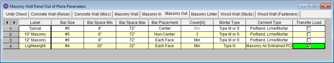
This is the main vertical bar size that will be used for axial/out of plane design.
This allows you to give a maximum and minimum bar/grout spacing. If you give a range between the max and min, then the program will optimize the reinforcement spacing according to strength requirements (code checks).
This defines how the reinforcement is placed in the wall region.
Center will put a single bar centered in a given cell.
Non-Center will put a single bar non-centered in a given cell.
Each Face will put reinforcement on both faces of a given cell.
Staggered alternates the bars on either face along the length of the region.
Note:
Allows you to specify the distance from the exterior of the masonry block to the extreme fiber of the reinforcement. The default cover value is defined as Min. The Min input will use whichever governs between these two sections of the specification:
Thus, the Min term will create a cover equal to the maximum of tfaceshell + 1/2" OR 1-1/2".
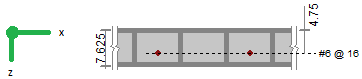
For any other cover you wish to impose simply overwrite the Min value with your value. If using the Non-Center option then the cover will always be from the +z local axis face of the wall.
For example, let's assume the wall shown below is using the "Non-Centered" reinforcement and the cover is set to 2.5". The image below shows exactly where this bar is then located in the wall (d = 7.625" - 2.5" - 3/8" = 4.75").
|
|
The actual "d" used in design will depend on the governing direction of loading. If load is applied in both out-of-plane directions to the wall then it is possible that a lower level of loading can produce a higher code check because the "d" is smaller in one direction than the other.
If a non-sensical value is defined (i.e. one where the bar does not fall inside of the block core then the program will give an error in the results and place the reinforcement just inside the faceshell of the block.
Note:
Allows you to specify the type of mortar/cement in the wall. This affects the modulus of rupture (flexural tensile stresses) from Tables 8.2.4.2 and 9.1.9.1.
This option will transfer out of plane loads from regions above and below openings into the regions adjacent to the openings. Note that the design of regions above and below openings will be omitted.
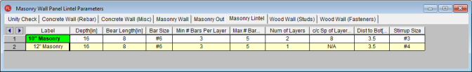
This is the total depth of your lintel.
This is the bearing length at either end of the lintel. This is used to calculate the effective length of the lintel.
This is the reinforcement size for your main reinforcing in the lintel.
This is the number of bars you wish to have in a given layer of reinforcement. If you give a range between the max and min, then the program will optimize the reinforcement spacing based on geometry of the section and also the number of layers that you have defined.
This is an option if you require multiple layers of reinforcement in the lintel.
This is the distance between layers (if there is more than one).
This defines the distance from the centerline of the lowest-most bar to the bottom fiber of the lintel.
This is the size of stirrup that will be added to the lintel if required.